

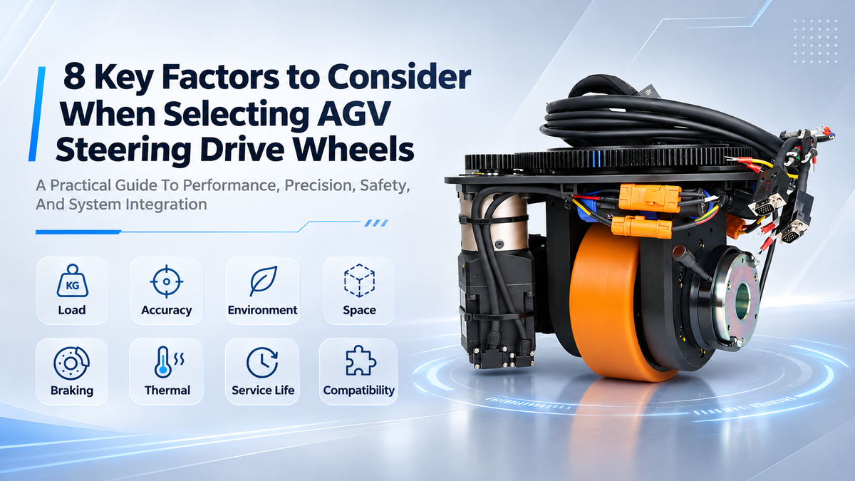
AGV steering drive wheels are key components of mobile robots. Their selection directly affects driving force, steering accuracy, running stability, and service life.
However, choosing the right steering drive wheel is not as simple as checking the load capacity, motor power, and wheel diameter. An AGV may have very different drive requirements when running with or without a load, on flat floors or slopes, and at low or high speeds.
Therefore, selecting the right AGV steering drive wheel requires a good understanding of the vehicle structure, working environment, control system, and long-term operating costs. Founded in 2013, HKT ROBOT has been a trusted manufacturer to provide standard and custom agv components for customers worldwide. Drawing on years of hands-on manufacturing expertise, we have summarized eight key factors that AGV manufacturers and engineers should consider.

1. Challenge 1: Matching Load Requirements with Driving Performance
An AGV's driving requirements depend not only on its total weight but also on acceleration, floor slope, rolling resistance, and load distribution. If the agv steering drive wheel is selected based only on the vehicle weight or rated payload, the motor may not provide enough torque. This can lead to difficult starts or wheel slipping when the AGV carries a full load uphill.
Solutions:
-
Calculate the required driving force: Consider vehicle weight, acceleration, rolling resistance, and floor slope.
-
Check output torque: Select the motor and gearbox based on wheel diameter, gear ratio, and transmission efficiency.
-
Consider drive wheel load distribution: Do not simply divide the total vehicle weight by the number of wheels. The center of gravity and chassis layout also affect the load on each drive wheel.
-
Allow a suitable safety margin: Consider peak torque, rotational inertia, and actual working conditions.
The required motor shaft torque can be estimated using the following formula:
T = (F × r) / (n × i × η)
Where:
-
F = Total driving force
-
r = Drive wheel radius
-
n = Number of drive wheels (assuming an even load distribution)
-
i = Gear ratio
-
η = Transmission efficiency
Note that this formula calculates the required torque at the motor shaft. When calculating output torque at the wheel, the gear ratio and transmission efficiency should not be included in the denominator.
Actual design should also consider drive wheel load distribution and tire-floor traction. Meeting the calculated torque requirement alone is not enough.
2. Challenge 2: Balancing Steering Accuracy and System Response
A high-resolution encoder does not automatically guarantee high positioning accuracy. Mechanical transmission errors and control system response also affect the actual performance of the steering drive unit.
For example, an AGV may vibrate when running at low speeds, fail to return to the target steering angle, or show differences in movement between multiple steering wheels.
Solutions:
-
Choose the right encoder: Select an incremental or absolute encoder based on positioning requirements.
-
Reduce mechanical errors: Pay attention to gearbox backlash and installation accuracy.
-
Optimize control settings: Make sure the steering zero position is calibrated correctly and servo parameters are properly adjusted.
-
Check synchronization: For AGVs with multiple steering wheels, verify that steering angles and wheel speeds are properly coordinated.
For high-precision AGVs, encoder resolution should not be the only selection factor. The performance of the complete drive system also needs to be tested.

3. Challenge 3: Adapting to Different Working Environments
Floor conditions, temperature, humidity, and contaminants can all affect wheel traction, wear, and operating stability. Different working environments also bring different challenges.
For example, low temperatures in cold storage facilities may affect the flexibility of polyurethane wheels and lubricant performance. Wet floors can reduce tire-floor traction and increase the risk of slipping. Metal dust and oil in automotive workshops may affect bearings and steering mechanisms. In cleanroom environments, wheel wear and particle contamination also need to be controlled.
Solutions:
-
Choose the right wheel material: Select suitable PU wheel materials and hardness based on the floor condition and load.
-
Consider temperature conditions: Choose suitable lubricants and sealing structures for the operating temperature.
-
Check protection ratings: Select the appropriate IP rating for motors and electrical components based on dust and moisture exposure.
-
Test under actual conditions: For special environments, carry out practical tests to check wheel traction and durability.
A harder wheel is not always more durable, and a higher IP rating does not necessarily make a product suitable for every application. The key is to match the wheel and protection design to the actual working environment.
4. Challenge 4: Balancing Omnidirectional Movement and Chassis Space
There is often a trade-off between steering flexibility and available chassis space. Low-profile AGVs have strict height requirements, while heavy-duty AGVs need enough space for the drive wheels, steering movement, and other components. If only the overall dimensions of the steering drive wheel are considered, mechanical interference may occur during installation or steering.
Solutions:
-
For narrow aisles and high maneuverability: Choose a dual-steering or multi-steering wheel configuration based on the vehicle's movement requirements.
-
For low-profile chassis designs: Check the installation height and available space for horizontal steering drive wheels.
-
For limited horizontal space: Consider a vertical steering drive wheel layout.
-
For in-place rotation or omnidirectional movement: Consider the number and position of steering wheels, as well as the control algorithm.
-
Check the mechanical layout early: Review installation height, steering clearance, cable routing, and ground clearance.
It is best to use 3D models during the design stage to check for possible interference between the steering drive wheels, battery, lifting mechanism, and other chassis components.
At HKT ROBOT, we have horizontal and vertical steering drive wheels, and we take all these factors into account to give you the right solution.
5. Challenge 5: Ensuring Reliable Braking and Slope Holding
AGVs need enough driving force, but they must also be able to stop safely under different conditions, including full-load operation, slopes, and emergency stops. This is especially important for heavy-duty AGVs and autonomous forklifts, where braking performance directly affects vehicle safety.
If engineers focus only on motor output torque and overlook the holding torque of the electromagnetic brake, the AGV may roll on a slope after stopping. In addition, using a standard holding brake for frequent dynamic braking may cause excessive heat and wear.
Solutions:
-
Calculate the required braking torque: Consider the fully loaded vehicle weight, maximum slope, drive wheel radius, and number of drive wheels.
-
Understand different braking methods: Electrical or regenerative braking through the servo drive is mainly used to slow down the vehicle, while an electromagnetic brake is generally used for holding and braking when power is off. They cannot simply replace each other.
-
Check brake specifications: Confirm the rated holding torque, installation position, gear ratio, and safety margin.
-
Test actual working conditions: Check full-load parking on slopes, power-off braking, and emergency stopping. Also confirm whether the brake is rated for the required dynamic braking conditions.
For example, consider an AGV with a fully loaded weight of 1,300 kg that needs to stop on a 5% slope. The downhill force caused by the slope alone is approximately 638 N. If the AGV uses two drive wheels with a diameter of 200 mm, each wheel needs to provide approximately 31.9 N·m of static holding torque at the wheel, assuming an even load distribution.
Actual selection should also consider braking safety margins, transmission efficiency, and brake installation position. If the brake is installed on the motor shaft, the required wheel-side torque must be converted to the motor shaft side.
6. Challenge 6: Managing Continuous Operation and Motor Temperature
The rated power and peak torque of a steering drive wheel do not fully represent its long-term operating capability. AGV running time, start-stop frequency, and load changes all affect the temperature of the motor, gearbox, and servo drive.
For example, a steering drive wheel may perform well during a short test but overheat after long periods of continuous operation or frequent starts and stops. If peak torque is used for too long, the motor may exceed its allowable thermal load. This can lead to overheating, drive protection, or reduced performance.
Solutions:
-
Check the motor duty type: Choose a suitable motor duty rating based on the actual operating cycle.
-
Understand rated and peak torque: Peak torque is normally available only for a specified period. It cannot replace the rated continuous torque for long-term operation.
-
Evaluate the operating cycle: Check daily running hours, start-stop frequency, full-load operating time, and maximum continuous running time.
-
Monitor temperature: Check the temperature of the motor, servo drive, and gearbox under actual loads to avoid long-term overloading.
For AGVs that operate for many hours each day, the motor load should be evaluated based on the actual working cycle. Full-load continuous running tests are also recommended. Motor power or a short no-load test alone cannot confirm whether a steering drive wheel is suitable for long-term operation.
7. Challenge 7: Balancing Purchase Cost and Service Life
A lower purchase price does not always mean a lower long-term cost. Low-cost products may lead to higher maintenance and downtime expenses.
During frequent and long-term operation, bearings, gearboxes, and polyurethane wheels gradually wear out. Without proper load evaluation and maintenance planning, components may need to be replaced more often, increasing downtime.
For example, according to the basic bearing life calculation method in ISO 281, the L10 life formula for ball bearings is:
L10 = (C / P)^3
Where:
-
C = Basic dynamic load rating
-
P = Equivalent dynamic bearing load
The calculated result is expressed in millions of revolutions.
Under the same conditions, if the equivalent dynamic load on a bearing doubles, its theoretical fatigue life drops to one-eighth of the original value. This shows why proper load control is important.
Note that L10 is a basic rating life based on specified conditions. It does not represent the actual service life of a bearing.
Solutions:
-
Evaluate key component life: Check the design life of bearings, gearboxes, and wheels.
-
Plan regular maintenance: Set inspection and maintenance schedules based on daily operating hours and start-stop frequency.
-
Consider modular design: Choose products that allow worn components to be replaced easily, reducing repair time.
-
Evaluate long-term costs: Consider purchasing, maintenance, spare parts, and downtime costs as part of the total life cycle cost (LCC).
8. Challenge 8: Ensuring Mechanical, Electrical, and Control System Compatibility
A steering drive wheel needs to work together with the motor, gearbox, servo drive, and vehicle controller. Even if each component meets its own specifications, this does not mean the complete system will be compatible.
In actual projects, mismatched motor voltage and servo drive specifications, incompatible encoder interfaces, communication problems, or unsynchronized steering between multiple wheels can all increase development and commissioning time.
Solutions:
-
Check electrical specifications: Confirm motor voltage, rated current, and peak current.
-
Match feedback and braking options: Select suitable encoders and electromagnetic brakes based on the control system.
-
Check communication compatibility: Confirm support for communication protocols such as CANopen, Modbus, EtherCAT, as well as physical interfaces such as RS485.
-
Test multi-wheel control: Check speed, steering, and braking coordination in systems with multiple steering drive wheels.
-
Consider vehicle safety: Verify emergency stops, communication loss, and braking functions as part of the complete vehicle safety design.
9. Partner with HKT ROBOT for Ideal AGV Steering Drive Wheels
Selecting an AGV steering drive wheel is not simply about comparing load capacity and motor power. It requires a balance between driving performance, steering accuracy, installation space, working environment, braking capability, and long-term operating costs.
At HKT ROBOT, we take all these factors into considerations, bringing over 10 years of expertise and specializing in main agv/amr components from agv steering drive wheels, differential drive modules, and agv servo motors to agv lifting and rotating mechanisms.
Plus, apart from standard agv components, we can provide customized solutions to meet different project needs based on your requirements.
We don't see agv steering drive wheels as a sinlge module. Instead, we will advise choosing them from an overall perspective with our hands-on over the years.
Send us your drawings or requirements if you are developing a new agv or amr project. Our team is online 24/7 to help you choose the most suitable and reliable agv steering drive wheels for you.
Paylaşmak:
AGV/AMR Drive System Troubleshooting: Motor, Servo Drive and Drive Wheel Problems